In the field of pneumatics and compressed air technology, control circuits are critical in managing actuator behavior in industrial environments where linear or rotary actuators control process valves that regulate the flow of materials. In many applications, especially in process industries, these valves direct different media through a system. In some cases, these materials must never mix due to safety or chemical compatibility concerns. Therefore, preventing the simultaneous operation of certain process valves is essential.
A practical example of avoiding this simultaneous valve operation arises in steel oven applications, where two different ingredients are controlled by separate process valves, such as a pneumatically operated knife gate valve and a butterfly valve. If the system relies on manual push-button valves for independent actuation, a significant risk is introduced where both process valves can be opened at the same time. If the materials they control are incompatible, this can lead to contamination, safety hazards, or process failure.
Pneumatic Interlocking as a Solution
A pneumatic interlocking system addresses this issue by ensuring that only one process valve is active at a time—so when one actuator operates, the other is automatically disabled. One effective approach strategically integrates a 3/2 (three-port, two-position) normally open (NO) pilot-operated valve into the control circuit. This arrangement allows compressed air to supply only one actuator at a time (Figure 1).
When one actuator receives air and begins movement, the system simultaneously cuts off the air-control pilot signal to the second actuator’s directional control valve. This creates a functional interlock between the two actuators, ensuring that the second process valve cannot be actuated while the first is in operation. For example, when the knife gate valve opens, the butterfly valve is isolated from the air supply, leaving it inoperable.
 Figure 1. The testing area where the engineers validated that the knife gate valve and the butterfly valve can be exclusively operated. Shown is the touch panel with the push button that operates the knife gate valve. Image courtesy of Motion.
How the Interlock Works
When one of the two push buttons is actuated, the secondary signal reaches the pilot port of the 3/2 NO pilot valve in the opposite circuit (Figure 2). As long as the button is held, the opposite circuit remains depressurized (inactive), and only one process valve can operate at a time. This design achieves fail-safe behavior through air exhaustion (Figure 3), allowing the pneumatic logic to enforce mutual exclusion between actuators using only pressure signals and valve switching states.
When Circuit A is active → Circuit B is disabled
When Circuit B is active → Circuit A is disabled
 Figure 2. How the interlock works: When one push button is actuated, the secondary signal reaches the pilot port of the 3/2 NO pilot valve in the opposite circuit. Image courtesy of Motion.
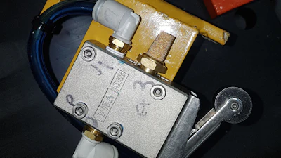
 Figure 3. The metallic silencers exhaust the ducted air outside the panel. Image courtesy of Motion.
Component Selection
The pneumatic circuit logic consists of two identical circuits, each responsible for controlling one process valve.
Each circuit includes:
- One 3/2 normally closed (NC) push-button valve.
- One 3/2 single-pilot NO valve.
- One 5/2 directional control valve controlling the actuator.
Under normal conditions, the operator presses the 3/2 NC push button. This action allows compressed air to pass through the push button and eventually control the opening or closing of the process valve. To activate the interlock, the signal generated by the push button is split into two paths:
- Actuation Path: This path actuates the corresponding 5/2 valve that operates the process valve (e.g., opening or closing the knife gate or butterfly valve).
- Interlock Path: This path crosses over to the opposite circuit and connects to the pilot port (port 10) of the 3/2 NO pilot valve in that circuit. This pilot signal forces that 3/2 valve to switch from its NO state to a closed state. As a result, the second circuit is exhausted and cannot transmit a control signal to its 5/2 directional control valve. Even if the operator presses the push button on the second circuit, no signal will reach the 5/2 valve, preventing the actuator from moving.
Enhancing Safety with Position Feedback
While pneumatic interlocking provides a strong level of functional safety, additional layers may be needed to further improve system reliability. In the steel oven application, a mechanical limit switch was installed at the end position of the knife gate valve actuator to indicate that the valve has fully closed (Figure 4). This mechanical feedback creates a dual-layer safety mechanism for the pneumatic interlocking system, preventing simultaneous actuation, unless safe operating conditions are verified.
 Figure 4. The mechanical limit switch, left, was installed at the end position of the knife gate valve, right, to provide feedback when it reached the end position. Image courtesy of Motion.
Required cleaning by authorized personnel is a unique instance where the process valves must open simultaneously. Figure 5 shows an example of two additional push buttons, pilot valves and OR gates (i.e., shuttle valves) that were added inside the panel to allow manual override of the pneumatic interlock.
 Figure 5. This circuit diagram example shows how the interlocking function with position feedback integration prevents overlapping operation of two process valves. The added buttons inside the panel allow manual override for certain situations. Image courtesy of Motion.
Choosing the Right Interlock Solution
Pneumatic interlocking is a practical and efficient method for ensuring safe operation in systems where multiple actuators control critical processes. There are many ways to implement interlocking in pneumatic systems, including more advanced safety-rated components and control architectures. However, the appropriate solution always depends on the application’s specific requirements. In the steel oven case, the requirement was relatively straightforward: preventing the overlapping operation of two process valves. This solution effectively protects the equipment and prevents the dangerous mixing of incompatible ingredients.
Ultimately, successful implementation depends on understanding the application, selecting the right components, and designing a system that meets both functional and safety needs.
Sylvain Desjardins is a certified fluid power pneumatic specialist at Motion with 40 years of experience in fluid power. Mutaz Shaban is a group automation manager at Motion with 23 years of experience in pneumatics. For more information, visit motion.com.