With today’s workforce shortage, more manufacturers are looking for ways to optimize machining operations and reduce cycle times. Record inflation makes lowering the cost per part machined more important than ever.
On the right parts and applications, machining with ceramic inserts can help. Please read on if you have previously tried ceramic inserts with unfavorable results. Ceramic inserts are not as forgiving and versatile as carbide inserts, so they demand extra care, but ceramic insert manufacturers have made good strides in improving the technology. To the end user, this means more savings and success on a broader base of applications.
Check Your Materials
First, ensuring your part material is acceptable for ceramics is essential. Hard steels of 38–70 Rockwell, gray cast iron, nodular iron, stainless steels over 35 Rockwell and difficult-to-machine high-temperature alloys are ideal for machining with ceramics. Titanium and softer steels are not—avoid machining them with ceramics.
Insert selection is more important than with carbide. The many options for insert materials include bidemics, SiAlON, silicon nitride, aluminum oxide, titanium carbide and whisker-reinforced ceramics. Many advanced coatings are available, which enhance performance but complicate selection. Here is a summary of what inserts work by material group:
- High-temp alloys: bidemics, SiAlON, whisker-reinforced
- Hardened steels: aluminum oxide, titanium carbide
- Cast iron: silicon nitride, aluminum oxide
Other Considerations
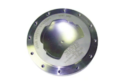
Choose the insert with the strongest shape to produce the part you are machining. The most common shapes, starting with the strongest type, are:
- Round
- 100° corner of an 80° diamond
- Square
- 80° diamond
- Triangle
- 55° diamond
- 35° diamond
Since ceramic is more brittle than carbide, choose a thicker insert for strength when possible.
 The higher up the scale, the stronger the shape, with round as the strongest. Choose the insert with the strongest shape to produce the part you are machining.NTK Cutting Tools.
The larger the angle, the stronger, but not as free cutting. The larger T-land inserts have a greater tendency for chip welding or built-up edge, primarily in high-temperature alloys. In those cases, a honed insert may be preferable. Most manufacturers match the grade with the edge preparation for optimal performance, but sometimes it takes some tweaking to a nonstandard edge preparation. The application may require a T-land with a hone.
Choose a tool holder for ceramic inserts with the largest lead angle to produce the part. Ceramic inserts will fit in an existing carbide tool holder and may work. The concern is using a worn tool holder or one without enough clamping force, allowing the insert to move in the pocket. This can cause edge chipping on the insert and even catastrophic failure.
A larger lead angle creates a chip-thinning effect like that of a round insert. This allows for a higher feed rate, reducing cycle time. It also allows the insert to lead with its strongest part into the cut, decreasing the chance of chipping or breakage.
Another consideration is that ceramic inserts need heat. These inserts will run 6 to 15 times faster than carbide, significantly increasing productivity. Here are some typical surface-feet-per-minute (SFM) cutting speeds:
- Milling of high-temp alloys at 2,000 to 4,000 SFM, depending on the alloy.
- Turning high-temp alloys at 600 to 1,700 SFM.
- Machining cast iron at 1,000 to 4,200 SFM.
- Hard-turning steels at 200 to 900 SFM.
When programming, keep the insert in the cut as much as possible in turning and milling. Milling is an interrupted cut, so the insert does come out of the cut, but keep the cutter as engaged as possible. Do not run coolant when milling, for two reasons. One, the insert needs heat; two, it increases the chance for thermal cracking and then thermal chipping—leading to premature tool life. The insert comes out of the cut very hot; dousing it with coolant causes thermal shock. Some of the new grades for turning can be run with coolant, but it is best to run dry in most cases. Also, run dry when turning with interrupted cuts.
If there is depth-of-cut chipping or notching, increase the edge preparation. This is most common on materials with scale or roughness on the part’s outer diameter (OD). If turning or milling with multiple passes, vary the depth of cut.
Bottom line
The extra effort is worth the reward. There are real-life examples of implementing ceramic inserts and reducing cycle time from 1½ hours to 5 minutes. Once you or your team learn this new skill and have some success, the savings will continue to come job after job. The tips in this article should lead you onto the right path, but for further assistance, engaging your qualified vendors will confirm that you have the best application solutions.
About the Author
With 35 years of industry experience, Jerry Kronenberger is currently Motion’s sales manager for the specialty division, focusing on cutting tool, abrasive and coolant solutions for metalworking manufacturers. He previously worked at Goodrich Aerospace as a tool engineer and Seco Tools as a sales engineer. Kronenberger is a past president of the Dayton Region Manufacturers Association.
For more information, visit www.motion.com.