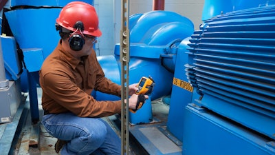
Thermal imagers and cameras work best to troubleshoot equipment issues when the equipment is running. Electrical equipment must be under at least 40 percent of nominal load to detect problems—although maximum load conditions are ideal, if possible. This includes motors, drives, and their associated electrical connections, wiring, fuses, and transformers. Thermal images indicate surface temperature of these different components and allow the user to determine next best steps, which might include further analysis, a fix, or replacement.
With thermal imaging, for the most part, you’re looking for hot spots in equipment, which is why it’s critical that the equipment be running to at least 40 percent of nominal load. While thermal imaging does provide immediate, in-the-moment information about malfunctioning equipment, it is also useful for building heat profiles.
Motors
Start by building heat profiles of your motors—these are simply high-quality thermal images of the motor running under normal operating conditions. This gives you a baseline of temperature measurements you can use later if/when the equipment has issues. The thermal images should include all the critical components such as the motor, shaft coupling, motor and shaft bearings, and the gearbox.
When inspecting low-load situations, be sure to note all possible problems, even if they reflect only a small temperature difference. As a load increases, the temperature will increase and if a problem exists, expect greater temperature differences at higher loads. All motors should list the normal operating temperature on the nameplate. Abnormal temperatures, which show up on a thermal imaging inspection, may indicate inadequate cooling, power quality issues, impending bearing failure, insulation failure, and/or shaft misalignment.
Three-Phase Imbalance
Capture thermal images of all electrical panels and other high-load connection points such as drives, disconnects, controls, and so on. Wherever you discover higher temperatures, follow that circuit, and examine associated branches and loads.
Compare all three phases side by side and check for temperature differences. A cooler-than-normal circuit or leg might signal a failed component. More heavily loaded phases will appear warmer. Hot conductors may be undersized or overloaded. However, an unbalanced load, an overload, a bad connection, and harmonics all create a similar pattern, so follow up with electrical or power quality measurements to diagnose the problem.
Connections and Wiring
Look for connections that have higher temperatures than other similar connections under similar loads. That could indicate a loose, over-tightened, or corroded connection with increased resistance. Connection-related hot spots usually, but not always, appear warmest at the spot of resistance, cooling with distance from that spot.
In some cases, a cold component is abnormal due to the current being shunted away from the high-resistance connection. You may also find broken or undersized wires or defective insulation. The NETA (InterNational Electrical Testing Association) guidelines say that when the difference in temperature (DT) between similar components under similar loads exceeds 15 °C (~25 °F), immediate repairs should be undertaken.
Fuses
If a fuse shows up hot on a thermal scan, it may be at or near its current capacity. However, not all problems are hot. A blown fuse, for example, would produce a cooler-than-normal temperature.
Motor Control Centers (MCC)
To evaluate an MCC under load, open each component and compare the relative temperatures of key components: bus bars, controllers, starters, contactors, relays, fuses, breakers, disconnects, feeders, and transformers. Incorporate the guidelines previously provided in this article for inspecting connections and fuses and identifying phase imbalance.
Tip: Measure the load at the time of each scan so that you can properly evaluate your measurements against normal operating conditions.
Transformers
For oil-filled transformers, use a thermal imager to look at high- and low-voltage external bushing connections, cooling tubes, and cooling fans and pumps, as well as the surfaces of critical transformers. (Dry transformers have coil temperatures so much higher than ambient, it’s difficult to detect problems with thermal imagery.) Incorporate the guidelines previously provided for connections and imbalances.
The cooling tubes should appear warm. If one or more tubes is comparatively cool, oil flow is probably restricted. Keep in mind that, like an electric motor, a transformer has a minimum operating temperature that represents the maximum allowable rise in temperature above ambient (typically 40 degrees Celsius). A 10-degree Celsius rise above the nameplate operating temperature will probably reduce the transformer’s life by 50 percent.
Justin Sheard is a Senior Engineer and Application Specialist with the Fluke Industrial Imaging group.